The choice of the tips and dies, in terms of their dimensions and geometric conformation and shape, is an important factor for the extrusion process. The tips and dies can be classified according to: construction characteristics and geometric/processing characteristics.
CONSTRUCTION CHARACTERISTICS
Concerning the construction characteristics, the tools can be differentiated by:
- fixing system, mainly for the tips which can be conic or with thread;
- material and production process.
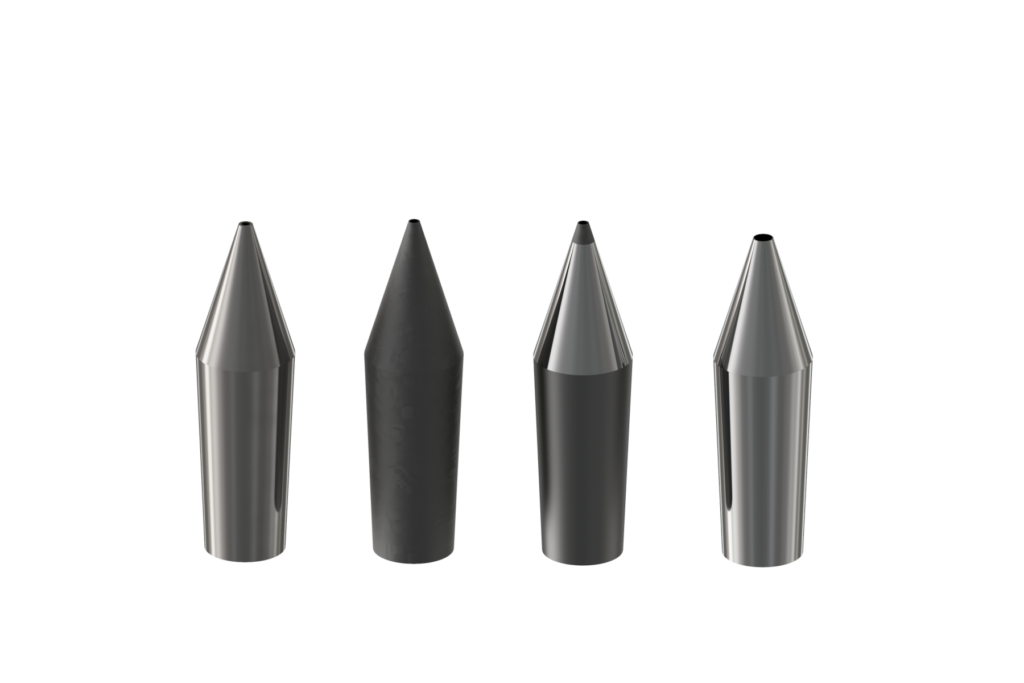
The tools can be classified in according with the material with which they are built.
The material normally used for tips and dies construction are:
Steel AISI304 o AISI316
It is normally used only in particular case in order to avoid deformation of the tip holder and die holder.
Hardened steel
Standard Hardened steel
Hardened stainless steel such as: AISI 420-X20Cr18, AISI 420B-X30Cr18, Stavax, etc
Nitrated Steel
41CrAlMo7, 34CrAlNi7, 34CrAlMo7, Impax, etc.
Tungsten Carbide or Widia (from german Wie Diamant: Like diamond).
There are many type and quality of tungsten carbide, the choice must be made according to the type of production process and processing needs.
The type of tungsten carbide used (K01 – K05 – K10 – K20 – K30 – K40) acts on quality of the tips and dies, their cost, wear resistance and life time.
|
TUNGSTEN CARBIDE |
HARDNESS HV |
|
K01 |
1800 |
|
K05 |
1750 |
|
K10 |
1700 |
|
K20 |
1600 |
|
K30 |
1450 |
|
K40 |
1295 |
THE TIPS AND DIES ARE NOT OF THE SAME QUALITY! The quality depends on the type of tungsten carbide used.
Steel with tungsten carbide insert
The inserts can be placed into the hardened tip/die by brazing process or by mechanical pressure. The way how to place the insert depends on the insert dimension, hole dimension, concentricity, eccentricity and diameter tolerance required and working temperature. Different type and shaper of insert can be realized and applied in according with the product to be realized and wear resistance need.
Steel with diamond insert
The insert is placed into the not tempered tip/die.
Steel with PVD treatment (Physical Vapour Deposition), etc.
The PVD treatments increase the surface hardness of the components (micro-hardness), reduce the friction coefficient and can be realized using different materials and different substrates in:- Titanium Nitride (TiN)
- Chromium Nitride (CrN)
- Zirconium Nitride (ZrN)
- Titanium Carbonitride (TiCN)
- Chromium Carbonitride (CrCN)
- Zirconium Carbonitride (ZrCN), etc.
The PVD type has to be chosen in according with production and process needs.
Hastelloy
Normally used to process fluoropolymers due to its high corrosion and oxidation resistance.
The choice has to be made according to:
- Wire/Cable and Fibers characteristics and property;
- Compounds property;
- Line speed, production speed;
- Tip and Die dimension, wire and cable dimension;
- Tolerance in terms of diameter, ovalization, concentricity, etc.;
- Operation and production needs.
GEOMETRIC AND PROCESSL CHARACTERISTICS
The tips and dies can be classified even according to their shape and geometric and processual characteristics: Semi-compression, Compression, Tube, Semi-tube, Mixed conformation.
The choice has to be made even in according with the compound to be extruded and the process type (Insulation, Sheathing, Filling, Jacketing, etc.). Equally important is the tools chamber or flowing chamber. The flowing chamber consider the dimensions and shape of material flow through the tools. The design of the flowing chamber acts on the extruder back pressure, pressure of the plastic on the wire, plastic adhesion, quality of the cable’s surface, etc.
In conclusion, two couples of tips and dies having the same diameters can easily have and generate different flowing chamber influencing:
- Quality and final characteristics of the cable;
- Extruder working back pressure;
- Quality of the surface, etc.
The flowing chamber must be flawless in its geometry and its section variation and of course in tune with flow distributor dimensions (Main flow distributor, Die holder) e distributor “leakage gap”.
The working pressure depends even on the extrusion screw and barrel design. The screw design, according to the screw rpm, act directly on the material viscosity at the cross head entrance.
The design of the tools chamber, together with channel dimension of the flow distributor, dimension of the distributor at the material entrance, dimension of the distribution and pumping channels, has an huge impact on the extruder working pressure as well as on the cable quality.
The working pressure limit is defined by the extruder producer and it depends on the extruder characteristics in terms of dimensions, material and screw and barrel design.
Too high working pressure acts on:
- Cable quality
- Max Production Speed
- Line acceleration ramp.
- Compound over-heating
Mechanical deformation of the head components, clamp opening. These can generate leakage of plastic during the production through the mechanical connection of the extruder and head components.
Premature wear of the extrusion screw, flow distributors, rings, etc.
Operator Safety. Too high pressure can generate breaking of the extruder clamp/Jaw, head collar/connection, etc.
In conclusion the choice of the proper tools, in terms of tip and die hole diameter and in terms of the material with which they are built, is an important condition in order to guarantee the high wear resistance and repeatability and constant cable quality.