In the extrusion process an important role is played by extruder screw, flow distributor design, ring for skin and stripes design, tools chamber. They must be designed in according with the compound property and rheology to be processed, minimum and maximum extruder output and type of process.
Most of the roles used for screw calculation can be applied for the flow distributor and skin ring calculation.
The extrusion screw can be easily divided in different zones: feeding, compression-melting, mixing, pumping.
The screw can be classified according to its conformation: single compression screw, single barrier, dual or multi barrier, barrier with mixing device.
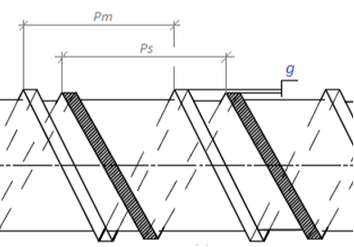
Regarding the barrier screws, many factors must be considered such as pitch of the main thread, pitch of the supplementary thread (in the barrier zone or mixing zone), leakage gap for the correct barrier function and mixing effect. This is changing in according with screw dimension and compound to be extruded.
The compression of the screw can be fast compression (Compression length Lc < 5D) or progressive (Compression length Lc > 5D).
The choice of the compression length depends on type of the compound to be extruded, extruder characteristic, extruder dimension, extruder barrel design, extruder rpm, production speed, extruder output.
The compression ratio can be:
– linear compression ratio;
– volumetric compression ratio;
– axial compression ratio in the barrier or mixing zones;
– axial decompression ratio in the barrier zone for high viscosity compounds (LS 0H, HFFR, XLPE FR, etc.).
The linear compression ratio can be quickly calculated considering the heght of the thread on the feeding zone and pumping zone of the screw.
C.R. = Ha/Hp
The volumetric compression ratio, against the linear compression ratio, considers the volume reduction passing from the feeding zone throught he pumping zone of the screw. It can be calculated with the fornula:
C.R. = [(D – Ha)*Ha] / [(D – Hp)*Hp]
D: Barrel diameter
Ha: Heigh of the thread on the feeding zone
Hp: Height of the thread in the pumping zone
An important role is even played from the length of the compression zones.
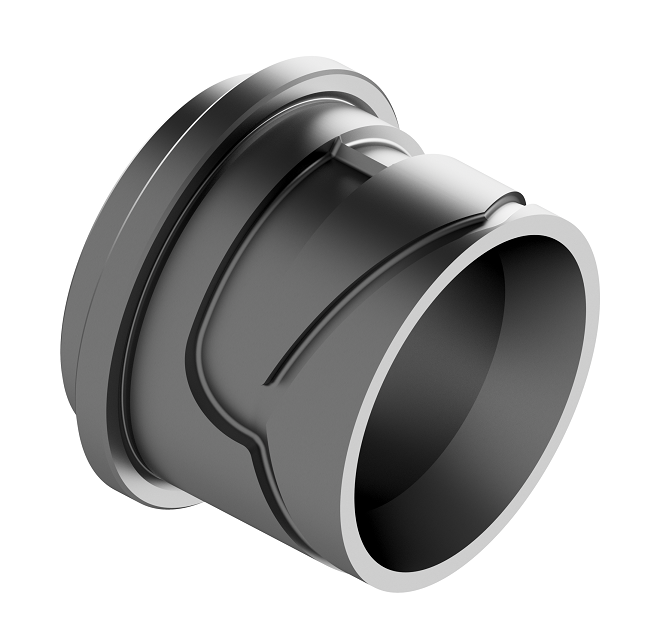
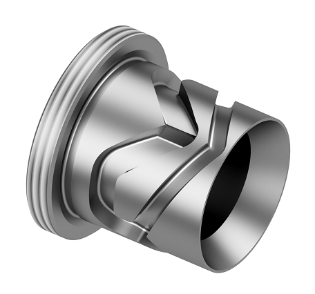
The barrier zone and the leakage zone is present even on the flow distributor and ring for skin. As per the screw design, the leakage gap depends on the compound to be extruded, output to be deliveried, flow channel dimensions, etc.
Equally important are the dimensions of the flow channels into the distributor, in terms of depth, width, section variation and flow path.
The flow channels can be classified in feeding channels, distribution channels and pumping channels.
For the correct ring calculation many factors must be considered, such as:
– ring nominal diameter or distributor nominal diameter;
– ring or distributor conicity (angle);
– type of the compound and its rheologic property;
– depth of the feeding channel and distribution path;
– feeding channel section, section variation and its path;
– leakage gap, even considering the layer thickness to apply and the extruder output;
– distribution channels section, section variation and it path and path lenght.
The wrong design of the flow distributor or ring for skin/stripe in terms of leakage gap, feeding and distribution channels can generate:
‒ wrong flow distribution;
‒ material leaking;
‒ too high extruder back pressure;
‒ too low extruder back pressure and unstability of the extruder output;
‒ compound over-heating;
‒ skin/layer defects, roughness, unstable thickness distribution;
‒ wrong/skin distribution around the cable surface;
‒ skin layer not closed and presence of longitudinal lines.
The leakage gap, the leakage lenght as well as the variation of the feeding and distribution channels section depend on:
– rheology of the compound to be processed;
– extruder output;
– dimension of the cable;
– dimension/thickness of the layer to be produced.
Together with the correct design of the flow distributor and/or ring for skin, the proper chamber flowing into the tools must be performed.
The tools chamber can act on:
– extruder working back-pressure;
– shear rate e shear stress on the compound;
– adhesion of the compound on the cable/wire;
– wire stretching that is inversely proportional with extruder back pressure. Higher pressure into the extruder generate lower adhesion of the compound on the cable and lower stretching effect;
– quality of the cable surface.